Abstract
This technical paper examines the engineering principles and performance characteristics of Con-form Group's Span+ rafter-mount HVAC platform system. Through collaborative research with Charles Sturt University and the University of Sydney, the Span+ system demonstrates the capability to achieve spans exceeding 12 metres using light gauge steel construction while maintaining an 83% weight reduction compared to traditional structural steel alternatives. This analysis presents the material properties, structural design methodology, load distribution mechanics, and compliance testing that validate Span+ as a superior alternative for HVAC equipment support where purlin capacity is insufficient.
1. Introduction
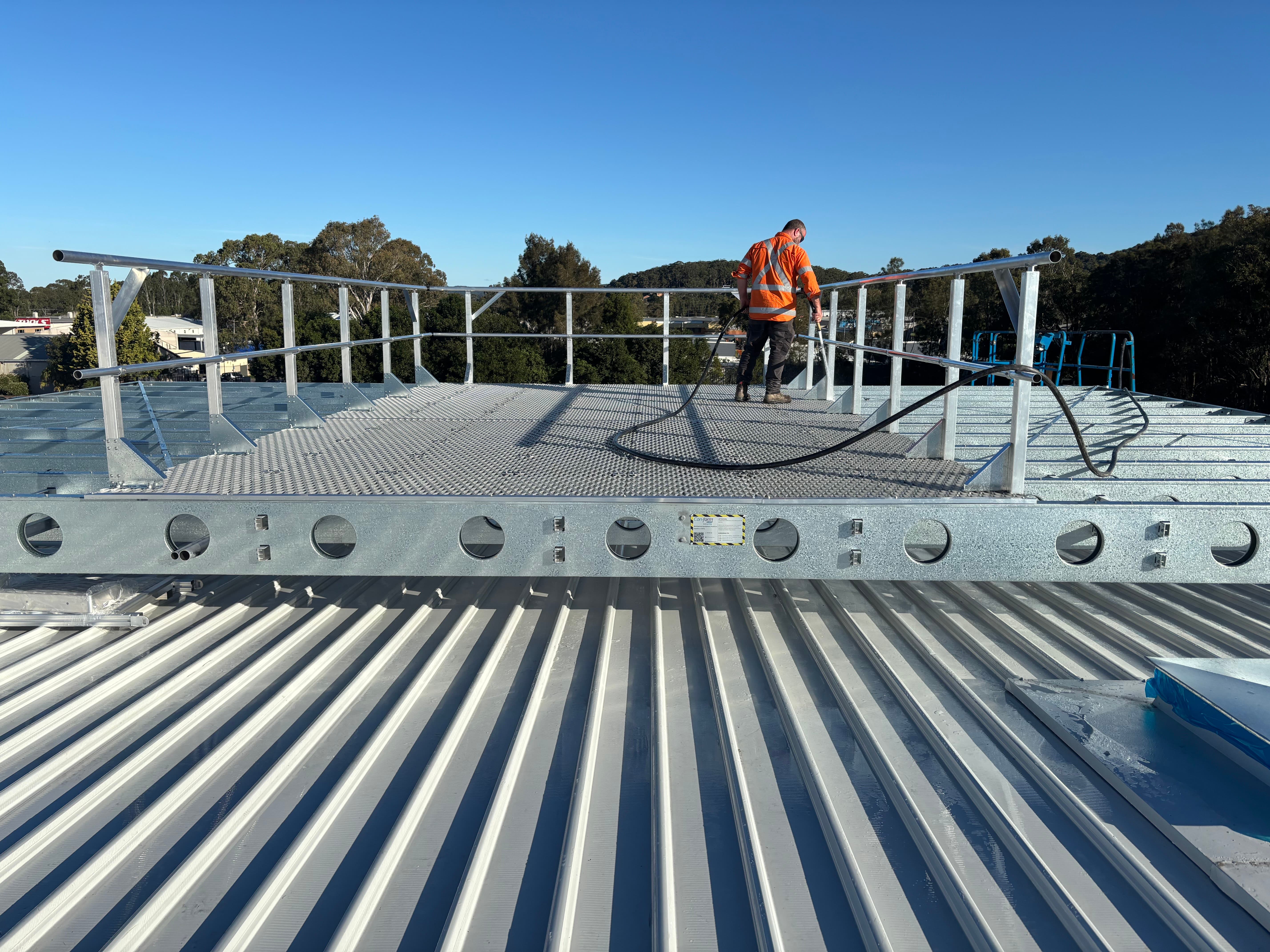
The increasing complexity and weight of modern HVAC equipment, particularly in data centre and commercial applications, has created significant challenges for structural engineers designing rooftop support systems. Traditional structural steel platforms, while robust, impose substantial dead loads on existing structures and require extensive crane operations and hot works during installation. The Span+ system (Code: SPNPLS+) represents a paradigm shift in long-span platform design through the application of advanced light gauge steel engineering.
2. Material Specifications and Properties
2.1 Base Material
The Span+ system utilises Australian-made ZINCALUME® G550 light gauge steel, featuring:
- Minimum yield strength: 550 MPa
- Coating mass: AZ150 (150 g/m² aluminum-zinc alloy coating)
- Base metal thickness range: 1.2mm - 3.0mm (application dependent)
- Corrosion resistance: 25-year warranty performance in Australian conditions
2.2 Material Advantages
The G550 grade provides superior strength-to-weight ratio compared to traditional G250/G350 structural steel:
- Yield strength 2.2x greater than G250
- Enables thinner sections while maintaining structural integrity
- Self-healing properties of aluminum-zinc coating
- No requirement for additional protective coatings
3. Structural Design Methodology
3.1 Load Path Engineering
The Span+ system employs a proprietary truss design that optimises load distribution through:
Primary Load Path:
- Point loads from HVAC equipment → Deck mesh
- Deck mesh → Secondary bearers
- Secondary bearers → Primary trusses
- Primary trusses → Rafter connection points
3.2 Truss Configuration
The system utilises a modified Warren truss configuration with:
- Top chord: Continuous C-section profiles
- Bottom chord: Continuous C-section profiles
- Web members: Alternating diagonal struts
- Connection methodology: Mechanical fastening (no welding required)
3.3 Span Capability Analysis
Through finite element analysis (FEA) and physical testing, the following span capabilities were validated:
Span DistanceLive Load RatingDeflection LimitSafety Factor6m5.0 kPaL/2502.58m5.0 kPaL/2502.510m3.5 kPaL/2502.512m2.5 kPaL/2502.5>12mProject specificL/2502.5
4. Load Testing and Validation
4.1 University Collaboration Testing Program
In partnership with Charles Sturt University and the University of Sydney, comprehensive testing included:
Physical Load Testing:
- Progressive loading to 2x design capacity
- Deflection monitoring at 0.5 kPa intervals
- Strain gauge analysis at critical connection points
- Fatigue testing under cyclic loading conditions
Theoretical Validation:
- FEA modeling using STRAND7 and SpaceGass
- Non-linear buckling analysis
- Dynamic response evaluation
- Connection capacity verification
4.2 Performance Results
Key findings from the testing program:
- Actual capacity exceeded theoretical predictions by 15-20%
- Deflection remained within L/300 at design loads
- No permanent deformation at 1.5x design load
- Connection integrity maintained throughout testing
5. Wind Load Compliance
5.1 Design Standards
The Span+ system is certified to AS/NZS 1170.2 for wind regions A, B, and C:
Region A (W32): V₁₀₀₀ = 32 m/sRegion B (W41): V₁₀₀₀ = 41 m/sRegion C (W50): V₁₀₀₀ = 50 m/s
5.2 Wind Load Calculations
For a typical installation at 15m height:
- Terrain Category 3
- Shielding multiplier: 1.0
- Topographic multiplier: 1.0
Design wind pressure:qᵤ = 0.5 × ρ × V²des × Cfig × Cdyn
Where aerodynamic shape factors for the open frame design significantly reduce wind loading compared to solid platforms.
6. Comparative Analysis: Span+ vs Structural Steel
6.1 Weight Comparison
For a typical 10m × 6m platform supporting 5 tonnes of equipment:
SystemPlatform WeightTotal Dead LoadWeight ReductionStructural Steel4,200 kg9,200 kg-Span+ LGS720 kg5,720 kg83%
6.2 Installation Efficiency
Structural Steel Requirements:
- 50-tonne crane for 2-3 days
- Hot works permits and welding
- 6-8 skilled welders/riggers
- Installation time: 3-5 days
Span+ Requirements:
- 20-tonne crane for 2-4 hours (delivery only)
- No hot works required
- 3-4 installers
- Installation time: 0.5-1 day
6.3 Structural Impact on Existing Building
The 83% weight reduction translates to significant benefits:
- Reduced rafter reinforcement requirements
- Lower seismic mass
- Decreased foundation loads
- Viable for retrofit applications where structural steel would exceed capacity
7. Connection Design and Seismic Performance
7.1 Rafter Connection Methodology
The Span+ system employs engineered stub columns that:
- Transfer loads directly to rafter positions
- Accommodate thermal movement
- Provide moment resistance for stability
- Allow for construction tolerances (±50mm)
7.2 Seismic Compliance
In accordance with AS 1170.4:
- Importance Level 2 structures
- Ductility factor μ = 2.0
- Structural performance factor Sp = 0.77
- Connection capacity designed for Ru = 1.0
8. Design Considerations for Engineers
8.1 When to Specify Span+
- Purlin capacity insufficient for equipment loads
- Spans between rafters exceed 6m
- Existing structure has limited reserve capacity
- Retrofit applications requiring minimal structural impact
- Projects requiring rapid installation
8.2 Load Calculation Example
For a 4-tonne chiller on a 12m × 8m platform:
Dead Loads:
- Platform self-weight: 12 × 8 × 15 kg/m² = 1,440 kg
- Equipment weight: 4,000 kg
- Total dead load: 5,440 kg
Live Loads:
- Maintenance access: 2.5 kPa × 96 m² = 24 kN
- Point load allowance: 1.8 kN
Total Design Load:
- ULS: 1.2G + 1.5Q = 1.2(53.3) + 1.5(24) = 100 kN
- Distributed load on rafters: 100 kN ÷ 4 rafters = 25 kN per rafter
8.3 Specification Checklist
Engineers should provide:
- Rafter positions and spacing
- Equipment layout and weights
- Maintenance access requirements
- Wind region and terrain category
- Seismic hazard factor
- Integration requirements (screens, walkways)
9. Sustainability and Lifecycle Considerations
9.1 Environmental Impact
- 100% recyclable steel content
- Reduced transport emissions (83% lighter)
- Minimal site disturbance (no concrete, no welding)
- Lower embodied energy than structural steel
9.2 Lifecycle Cost Analysis
Over a 25-year design life:
- No repainting required (ZINCALUME coating)
- Reduced crane costs for future equipment changes
- Modular design allows reconfiguration
- Full material recovery value at end of life
10. Case Study: Data Centre Application
Project: 40 MW data centre, Western SydneyChallenge: Support 48 × 30-tonne chillers on existing structure
Traditional Approach:
- Structural steel platforms: 125 tonnes
- Rafter reinforcement required
- 4-week installation program
- Cost: $1.2M
Span+ Solution:
- Platform weight: 21 tonnes
- No rafter reinforcement
- 5-day installation program
- Cost: $680k
- Result: 43% cost saving, 80% time saving
11. Conclusion
The Span+ system demonstrates that light gauge steel technology can successfully address the limitations of traditional structural steel in long-span applications. Through innovative engineering, rigorous testing, and optimised design, the system achieves:
- Spans exceeding 12 metres
- 83% weight reduction
- 5× faster installation
- Full compliance with Australian Standards
- Significant cost advantages
For structural engineers facing challenging retrofit projects or seeking to optimise new construction, Span+ provides a validated, high-performance alternative that reduces structural demands while maintaining safety factors appropriate for critical HVAC infrastructure.
12. References
- AS/NZS 1170.0:2002 Structural design actions - General principles
- AS/NZS 1170.1:2002 Structural design actions - Permanent, imposed and other actions
- AS/NZS 1170.2:2011 Structural design actions - Wind actions
- AS/NZS 1170.4:2007 Structural design actions - Earthquake actions
- AS/NZS 4600:2018 Cold-formed steel structures
- AS 1397:2011 Continuous hot-dip metallic coated steel sheet and strip
- AS 1657:2018 Fixed platforms, walkways, stairways and ladders
Appendix A: Load Tables
[Detailed span tables for various configurations available upon request]
Appendix B: Standard Details
[CAD details and specifications available for download at con-formgroup.com.au]
For technical enquiries and project-specific engineering support:Con-form Group Engineering DepartmentEmail: engineering@con-formgroup.com.auPhone: 1300 882 490