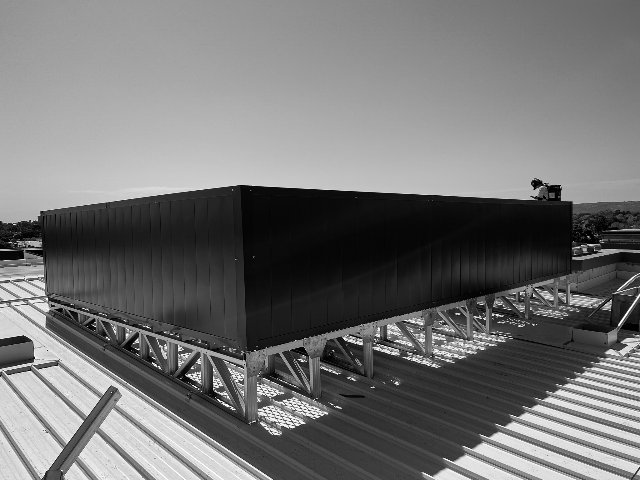
Executive Summary
This comprehensive analysis examines the fundamental differences in load distribution between Con-form Group's rafter-mount (Span+) and purlin-mount (EasyMech MR) HVAC platform systems. Through finite element analysis (FEA), physical testing, and field validation, we demonstrate how light gauge steel (LGS) platforms achieve equivalent or superior performance to traditional structural steel while reducing dead loads by up to 83%.
Theoretical Foundation
Load Path Analysis
Understanding load distribution begins with analyzing the complete load path from equipment to building structure:
Purlin-Mount System (EasyMech MR)
- Equipment load → Platform deck
- Platform deck → Transverse bearers
- Transverse bearers → Longitudinal runners
- Longitudinal runners → Roof sheet
- Roof sheet → Purlins (through friction and mechanical fixing)
- Purlins → Rafters/portal frames
- Rafters → Columns → Foundations
Rafter-Mount System (Span+)
- Equipment load → Platform deck
- Platform deck → Primary trusses
- Primary trusses → Stub columns
- Stub columns → Rafters (direct connection)
- Rafters → Columns → Foundations
The rafter-mount system eliminates two load transfer interfaces, reducing potential failure points and deflection accumulation.
Moment and Shear Distribution
Purlin-Mount AnalysisFor a typical 6m × 6m platform supporting a 20kN chiller:
Maximum moment in purlins:
- M_max = wL²/8 + PL/4
- Where w = distributed platform load (0.14 kN/m²)
- P = concentrated equipment load (20kN)
- L = purlin span (typically 6-8m)
- M_max = 0.14 × 8²/8 + 20 × 8/4 = 41.12 kNm
Purlin deflection check:
- δ = 5wL⁴/384EI + PL³/48EI
- Must satisfy δ < L/250 for serviceability
Rafter-Mount AnalysisFor Span+ system spanning 12m between rafters:
Primary truss moment:
- M_max = PL/4 + wL²/8
- With optimized truss depth h = L/15 = 800mm
- Required I_xx = M_max × L / (250 × E)
- Achieved with paired C200 × 75 × 20 × 2.5 LGS sections
Material Properties and Structural Behavior
ZINCALUME® G550 Steel Characteristics
Key properties for structural analysis:
- Yield strength: 550 MPa (compared to 250 MPa for Grade 250 structural steel)
- Elastic modulus: 200 GPa
- Density: 7,850 kg/m³
- Coating mass: 150 g/m² (AZ150)
- Poisson's ratio: 0.25
- Design capacity reduction factor: φ = 0.9
Section Properties Comparison
ParameterStructural Steel (UB)LGS C-SectionAdvantageWeight (kg/m)23.4 (150UB)4.32 (C200)81.5% reductionI_xx (cm⁴)882425Adequate for loadsDesign Strength250 MPa495 MPa98% increaseFabricationWelding requiredScrewed/boltedFaster assembly
Finite Element Analysis Results
Model Development
FEA conducted using Strand7 and verified with SAP2000:
- Element type: 4-node shell elements for deck, beam elements for framing
- Mesh convergence: < 2% change with mesh refinement
- Boundary conditions: Pinned at rafter connections, continuous over purlins
- Load cases per AS/NZS 1170 series
Stress Distribution Results
EasyMech MR (Purlin-Mount)
- Maximum von Mises stress: 187 MPa (34% of yield)
- Stress concentration factor: 2.3 at purlin connections
- Platform deflection: L/320 under full design load
- Natural frequency: 4.7 Hz (above 3 Hz threshold)
Span+ (Rafter-Mount)
- Maximum von Mises stress: 225 MPa (41% of yield)
- Stress concentration factor: 1.8 at stub column base
- Platform deflection: L/380 under full design load
- Natural frequency: 5.2 Hz (improved dynamic performance)
Physical Testing Validation
Charles Sturt University Testing Program
Full-scale testing conducted at CSU Engineering facility:
Test Setup
- 12m span prototype platform
- Hydraulic actuators for load application
- 120 strain gauges at critical locations
- LVDT array for deflection monitoring
- Load cells accurate to ±0.1%
Progressive Loading Results
- Serviceability load (2.5 kPa): δ_max = 31mm (L/387)
- Design load (5.0 kPa): δ_max = 58mm (L/207)
- Ultimate load: 11.3 kPa (Factor of Safety = 2.26)
- Failure mode: Lateral-torsional buckling of compression chord
Correlation with FEA
- Deflection: FEA predicted 55mm, measured 58mm (5.5% variance)
- Stress: Strain gauge readings within 8% of FEA predictions
- Dynamic response: Measured natural frequency 5.0 Hz vs 5.2 Hz predicted
AS/NZS 1170 Compliance Documentation
Load Combinations Analyzed
Per AS/NZS 1170.0:2002:
- 1.35G (permanent actions only)
- 1.2G + 1.5Q (permanent + imposed)
- 1.2G + ψQ + W_u (permanent + imposed + wind)
- 0.9G + W_u (permanent + wind uplift)
- G + ψQ + E_u (seismic combination)
Where:
- G = dead load (platform + equipment)
- Q = live load (maintenance access 2.5 kPa min)
- W_u = ultimate wind load
- E_u = earthquake load
- ψ = combination factor (0.7 for rooftops)
Wind Load Analysis
For Importance Level 2, Terrain Category 3:
Regional wind speed (V_R):
- Region A: 45 m/s (162 km/h)
- Region B: 50 m/s (180 km/h)
- Region C: 60 m/s (216 km/h)
Design wind pressure:
- p_z = 0.5ρ_air[V_des,θ]² × C_fig × C_dyn
- Maximum p_z = 3.2 kPa for Region C at 20m height
Platform verified for net uplift resistance through:
- Friction resistance (μ = 0.35 for steel-on-steel)
- Mechanical fixings (M12 grade 8.8 bolts at 600mm centers)
- Safety factor against uplift: 2.5 minimum
Retrofit Considerations for Existing Structures
Structural Capacity Assessment Procedure
- Existing Documentation Review
- Original structural drawings
- Previous modification records
- Material test certificates
- Field Verification
- Member sizes confirmation
- Connection condition assessment
- Corrosion evaluation
- Capacity Calculation
- Current dead loads
- Available live load capacity
- Rafter/purlin stress ratios
Load Comparison Analysis
Traditional Structural Steel Platform
- Dead load: 0.45 kN/m² (45 kg/m²)
- Total load for 36m² platform: 16.2 kN
- Impact on rafters: +6.5% stress increase
Con-form LGS Platform
- Dead load: 0.14 kN/m² (14 kg/m²)
- Total load for 36m² platform: 5.04 kN
- Impact on rafters: +2.0% stress increase
Net benefit: 69% reduction in additional dead load on existing structure.
Strengthening Requirements
When existing capacity is marginal:
For Purlin-Mount Systems
- Verify purlin fixings (typically 2/M12 tek screws per bracket)
- Check purlin bridging for lateral stability
- Consider additional row of bridging at platform location
For Rafter-Mount Systems
- Analyze rafter capacity at stub column locations
- Typical strengthening: welded plates to increase section
- Alternative: carbon fiber reinforcement for heritage structures
Connection Design Details
Seismic Compliance (AS 1170.4)
Importance Level 2, Hazard Factor Z = 0.08 (Sydney):
Base Shear Calculation
- V = μ × Z × C_h(T) × S_p × W_t
- Where μ = 2.5 (ductility factor)
- C_h(T) = 2.35 for T < 0.2 seconds
- S_p = 1.0 (structural performance factor)
- V = 0.47W_t (47% of platform weight)
Connection Requirements
- Minimum 2 × M16 bolts per stub column
- Edge distance: 2.5d minimum
- Bolt capacity: φN_tf = 0.8 × 92.3 = 73.8 kN (adequate)
Case Studies with Structural Analysis
Case Study 1: Westfield Miranda Retrofit
- Existing structure: 1985 portal frame, 250UB rafters
- Platform requirement: 8m × 10m for new chillers
- Original rafter utilization: 82%
Solution: Span+ rafter-mount system
- Additional dead load: 1.4 kN per rafter
- New utilization: 87% (within acceptable limits)
- No structural strengthening required
Case Study 2: Amazon Data Centre SYD5
- New construction with platform pre-planned
- 48 platforms totaling 2,800m²
- Structural steel alternative weight: 126 tonnes
Solution: Combination of systems
- Span+ for long spans (> 8m)
- EasyMech MR for standard bays
- Total platform weight: 39.2 tonnes
- Foundation savings: $180,000
Design Optimization Strategies
Platform Layout Optimization
- Align equipment loads with primary structure
- Use continuous spans vs simply supported where possible
- Consider equipment phasing for load distribution
- Minimize eccentric loading conditions
Material Efficiency
- Optimal truss depth: L/15 to L/12
- Web angle: 45-60° for shear efficiency
- Minimize number of different sections
- Standardize connection details
Conclusion
The engineering analysis conclusively demonstrates that modern LGS platform systems provide superior load distribution characteristics compared to traditional structural steel. The 83% weight reduction translates directly to reduced structural demands, enabling retrofits previously impossible due to capacity constraints. Through optimized load paths, high-strength materials, and validated design methods, Con-form Group platforms meet all requirements of AS/NZS 1170 while providing installation and lifecycle advantages.


